41 circuit diagram with labels
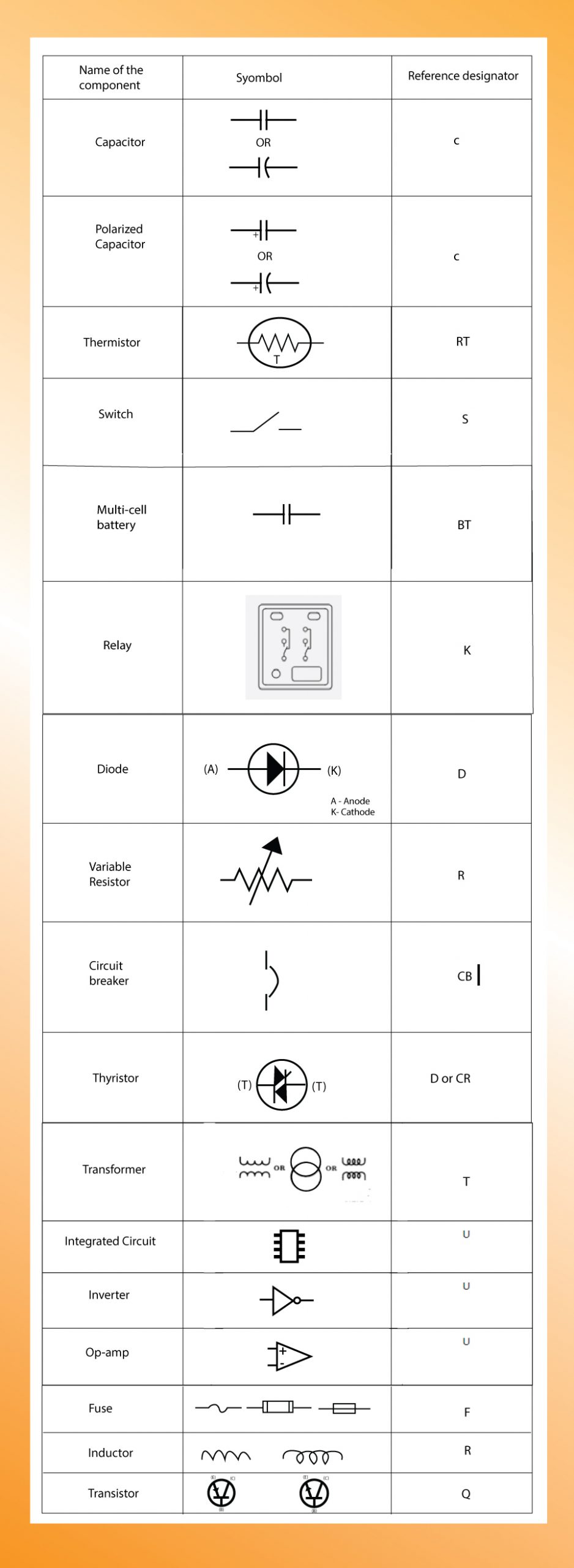
Circuit Diagram Symbols: A Complete List | EdrawMax - Edrawsoft The circuit symbols represent the various electrical and electronic components in a circuit diagram in the electrical and electronics world. Like transistors, ground, wires, bulbs, batteries, resistors, etc. Without these symbols, we will never be understood and analyze what the circuit diagram is trying to explain to us. Sample circuit diagrams from both the no labels (N) conditions: Only ... Specifically, the electrical circuits were graphically represented with real-life illustrations of circuit components from everyday devices, e.g., battery and light bulbs, as shown in Fig. 1 (b)....
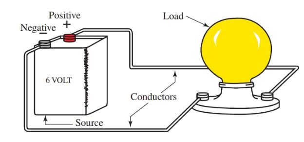
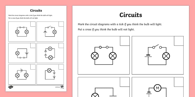
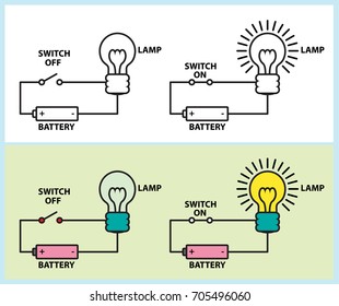
Electric Circuit Diagrams: Lesson for Kids - Study.com Take a look at the Simple Electric Circuit image. This simple circuit has four parts: the switch, the battery (which is the source of the electricity), the light bulb, and the wire through which...
Circuit diagram with labels
Circuit Diagram Symbols | Lucidchart Use power source symbols to indicate alternating and direct currents in a circuit diagram. Lucidchart has easy-to-use dialogs to let you switch the direction of the positive and negative charge icons, as well as the orientation and the voltage label. You can also make your circuit diagram stand out by adding a fill color with just one click. How to Draw a Circuit Diagram - Edraw - Edrawsoft Circuit diagrams are used by professionals to design, construct, and maintain circuits in rooms or structures. Students are also taught to use electrical diagrams to understand basic principles of power and electricity. A circuit diagram's benefit lies in the fact that it acts as a universal guide about circuit. How to Read Circuit Diagrams for Beginners - Starting Electronics Circuit Diagram Connections. Circuit diagrams or schematic diagrams show electrical connections of wires or conductors by using a node as shown in the image below. A node is simply a filled circle or dot. When three or more lines touch each other or cross each other and a node is placed at the intersection, this represents the lines or wires ...
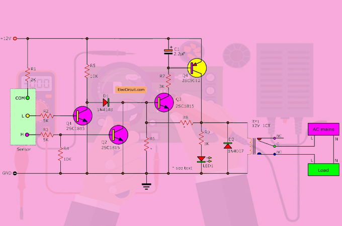
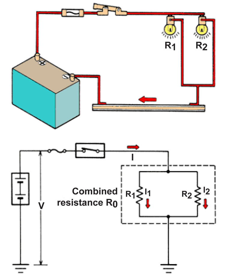
Circuit diagram with labels. Label the Electrical Circuit Schematic - InstrumentationTools Label the Electrical Circuit Schematic. Here we give you the basic full-wave bridge rectifier to identify the electronic components in the circuit. Next, you have to identify the labels in the electrical circuit schematic. Drag the letter that corresponds with the schematic label, drop it into the colored circle next to the correct symbol. How to Create an Electrical Diagram Using ConceptDraw PRO | Draw And ... The circuit diagram shows the scheme of a location of components and connections of the electrical circuit using a set of standard symbols. It can be use for graphical documentation of an electrical circuit components. The ability to create electrical diagrams and schematic using ConceptDraw PRO is delivered by the Electrical Engineering solution. Circuit symbols - Electric current and potential difference - KS3 ... We use circuit symbols to draw diagrams of electrical circuits, with straight lines to show the wires. The diagram shows some common circuit symbols. Some common circuit symbols Cells and batteries... A Tutorial for Beginners (Part 4)—Circuit Diagrams Using Circuitikz ... We then fill the environment with a single \draw command ending in a semicolon. \begin{ circuitikz } \draw ; \end{ circuitikz } The general format is then a pair of co-ordinates followed by a link and then the next pair of co-ordinates. You can then keep adding further links and co-ordinates like a chain.
Circuit Diagram Maker | Lucidchart Drop a power source component into your diagram and designate its label, orientation, and charge with the pop-up menu when you double-click it. Review and share Once you've added each element, including connections, ensure the circuit you've drawn behaves as expected. Share it with others or publish it in a presentation or as an image file. Labelling circuit diagrams | Solving D.C. Circuits - Science Campus Producing a diagram of an electrical circuit is a very important step in solving electrical circuit problems. The diagram below shows the circuit symbols for a cell and a resistor. It shows the e.m.f. (E) produced by the cell, the current (I) flowing through the circuit and the voltage drop (V) which occurs across the resistor. Note. Label system for making integrated circuit diagrams and printed circuit ... FIG. 2 is a top view label of a particular integrated circuit. FIG. 3 is a bottom view label of the same integrated circuit. FIG. 4 is a masking label corresponding to the label of FIG. 3 for use in making printed circuit board artwork. FIG. 5 is a perspective diagram useful in illustrating use of the masking label of FIG. 4. Electronics Schematics: Commonly Used Symbols and Labels The most common way to depict an integrated circuit in a schematic diagram is as a simple rectangle with leads coming out of it to depict the various pins. The arrangement of the pins in the schematic diagram doesn't necessarily correspond to the physical arrangement of pins on the IC itself.
How to Properly Set up Circuit Breaker Panel Labels - Krueger Electric 3. Number Each One of Your Circuit Breakers. The best way to set up your circuit breaker panel labels starts with numbering them effectively. We recommend starting with the circuit breaker at the top left column and labelling that as "1" and going down that column until you reach the end. Once you reach the bottom, jump back up to the top ... Circuit Diagram: How To Read And Understand Any Schematic A circuit diagram should be specific enough so that anyone can make the circuit just by following it. You don't actually need to understand it in order to build it. For example, look at the image above. I can buy a light-dependent resistor (LDR), a potentiometer, a resistor, an LED and a transistor. Then I can connect these on a breadboard by ... Label Series Circuit - Labelled diagram - Wordwall Label Series Circuit. Share Share by Iain. KS3 KS4 Physics Science. Show More. Like. Edit Content. Embed. More. Leaderboard. Show more Show less . This leaderboard is currently private. Click Share to make it public. This leaderboard has been disabled by the resource owner. This leaderboard is disabled as your options are different to the ... Circuit Diagram Maker | Free Online App - SmartDraw A circuit diagram allows you to visualize how components of a circuit are laid out. Lines connect fuses, switches, capacitors, inductors, and more. SmartDraw comes with thousands of detailed electrical symbols you can drag and drop to your drawings and schematics. Open an wiring diagram or circuit drawing template—not just a blank screen.
Labeling Voltages, Currents, and Nodes | Ultimate Electronics ...
Circuit diagram - Simple circuits | Electricity and Circuits | Don't ... We've seen the Symbols of the Most Common Electrical Components that are used to represent them. In this video, we will look at how to draw Circuit Diagrams ...
Labeling Voltages, Currents, and Nodes | Ultimate Electronics ...
Circuit Labels - Labelled diagram Circuit Labels. Share Share by Shaikha283931. Show More. Like. Edit Content. Embed. More. Leaderboard. Show more Show less . This leaderboard is currently private. Click Share to make it public. This leaderboard has been disabled by the resource owner. This leaderboard is disabled as your options are different to the resource owner. ...
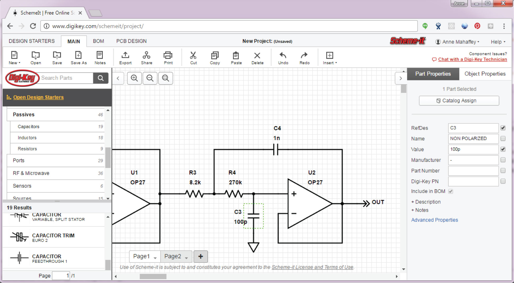
10 Best Free Online Circuit Diagram Makers in 2022
Label - Components - Circuit Diagram Label v1.0. by Circuit Diagram. d93dd6a8-4f47-441a-83d9-e3aa719a2ecb. Configurations. This component does not have any configurations. Properties. Text text. Compatibility. Web Editor. Command-Line. Desktop (Classic) Download.
Basic Electrical Circuit: Theory, Components, Working ...
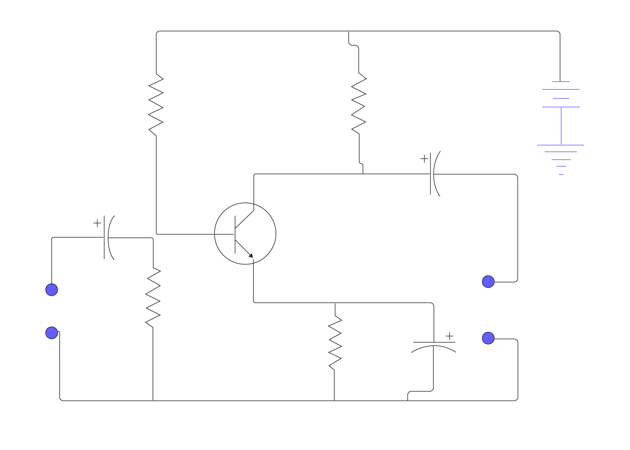
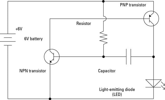
File:Transistor Simple Circuit Diagram with NPN Labels.svg File:Transistor Simple Circuit Diagram with NPN Labels.svg. Size of this PNG preview of this SVG file: 600 × 600 pixels. Other resolutions: 240 × 240 pixels | 480 × 480 pixels | 768 × 768 pixels | 1,024 × 1,024 pixels | 2,048 × 2,048 pixels | 720 × 720 pixels.
22,333 Circuit Diagram Images, Stock Photos & Vectors ...
Physics Tutorial: Circuit Symbols and Circuit Diagrams - Physics Classroom Use circuit symbols to construct schematic diagrams for the following circuits: a. A single cell, light bulb and switch are placed together in a circuit such that the switch can be opened and closed to turn the light bulb on. See Answer b. A three-pack of D-cells is placed in a circuit to power a flashlight bulb. See Answer 2.

Draw a simple electrical circuit and label the parts ...
Circuit Diagrams | Electronics Club Circuit diagrams for electronics are drawn with the positive (+) supply at the top and the negative (-) supply at the bottom. This can be helpful in understanding the operation of the circuit because the voltage decreases as you move down the circuit diagram. Circuit diagrams for science are traditionally drawn with the battery or power supply at the top. This is not wrong, but there is usually no advantage in drawing them this way and I think it is less helpful for understanding the circuit.
Draw a neat labelled diagram of a simple electric circuit ...
Circuit Diagram Tutorial: Explain with Examples and Templates - GitMind A circuit diagram is a diagram that displays an electrical current in diagrammatic form. A circuit diagram, also known as an electric circuit diagram, basic diagram, or electronic schematics, is a graphical depiction of an electrical circuit that is simpler. These diagrams are used to plan, develop, and maintain electronic devices.
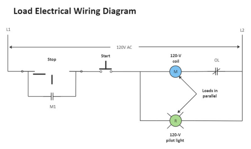
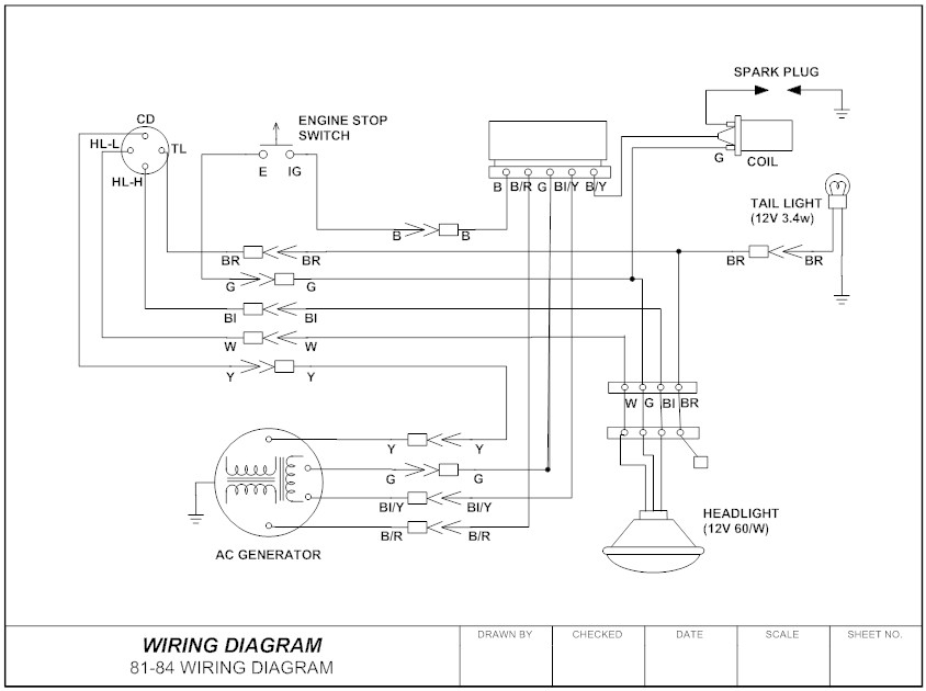
Wiring Diagram - Everything You Need to Know About Wiring Diagram
How to Draw Electrical Diagrams and Wiring Diagrams - SmartDraw How to Draw Electrical Diagrams. Making wiring or electrical diagrams is easy with the proper templates and symbols: Start with a collection of electrical symbols appropriate for your diagram. Draw circuits represented by lines. Drag and drop symbols to the circuits and connect them. Use line hops if any lines need to cross.
What are circuit diagrams? | Twinkl Teaching Wiki
How To Map Out, Label Your Electrical Panel/Fuse Panel Diagram The labeling electrical panel template Also by having the Excel file of this fuse box label, you can edit it at any time if you find mistakes on your fuse panel diagram, or change a circuit later...
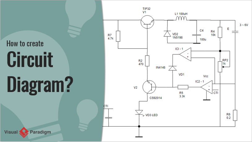
How to Create Circuit Diagram?
Circuit Diagram - A Circuit Diagram Maker Circuit Diagram A free, user-friendly program for making electronic circuit diagrams. Get Started Design Create diagrams visually by placing components with your cursor. Extend the built-in functionality with custom components. Render Export circuits as scalable vector images, or convert to a selection of other formats. Simulate
Wiring Diagram – A Comprehensive Guide | EdrawMax Online
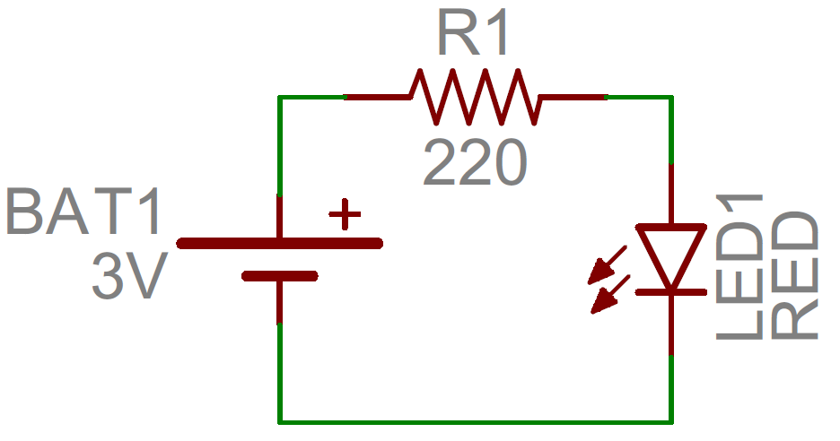
Circuit Diagram And Its Components - Explanation With Circuit Symbols A circuit diagram is a simplified representation of the components of an electrical circuit using either the images of the distinct parts or standard symbols. It shows the relative positions of all the elements and their connections to one another. It is often used to visually represent the circuit to an electrician. The following figure shows a simple circuit diagram.

Circuit Diagram of a Torch | Circuit diagram, Diagram ...
How to Read Circuit Diagrams for Beginners - Starting Electronics Circuit Diagram Connections. Circuit diagrams or schematic diagrams show electrical connections of wires or conductors by using a node as shown in the image below. A node is simply a filled circle or dot. When three or more lines touch each other or cross each other and a node is placed at the intersection, this represents the lines or wires ...
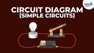
Circuit diagram - Simple circuits | Electricity and Circuits | Don't Memorise
How to Draw a Circuit Diagram - Edraw - Edrawsoft Circuit diagrams are used by professionals to design, construct, and maintain circuits in rooms or structures. Students are also taught to use electrical diagrams to understand basic principles of power and electricity. A circuit diagram's benefit lies in the fact that it acts as a universal guide about circuit.
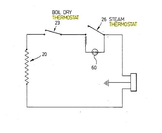
Standard Kettle Circuit Diagram | Karisimby's Blog
Circuit Diagram Symbols | Lucidchart Use power source symbols to indicate alternating and direct currents in a circuit diagram. Lucidchart has easy-to-use dialogs to let you switch the direction of the positive and negative charge icons, as well as the orientation and the voltage label. You can also make your circuit diagram stand out by adding a fill color with just one click.
Wiring Diagram - Everything You Need to Know About Wiring Diagram

Q2 Draw the circuit diagram to represent the circuit shown in ...
How to Read a Schematic - learn.sparkfun.com

Electricity - Circuits & symbols: Circuit diagrams

Solving a Simple Circuit Diagram With a Single Voltage Source ...
How To Draw Schematic Diagrams
What Is the Meaning of Schematic Diagram? | Sierra Circuits

Draw a simple electrical circuit and label the parts ...
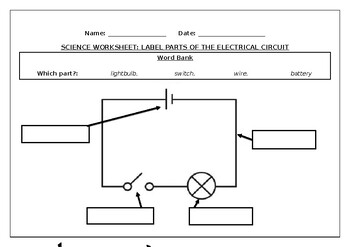
Science worksheet: Label parts of an electrical circuit by ...

Circuit diagram symbols , electrical symbols | electrical components
Circuit Diagram Maker | Lucidchart
The Simple Circuit
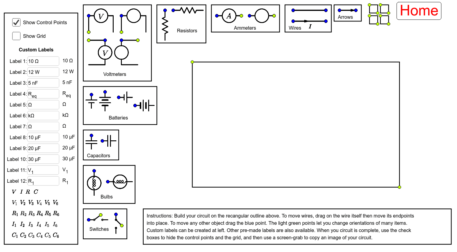
Circuit Diagram Maker: Browser Version – GeoGebra
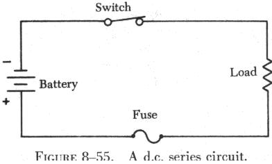
SERIESDCCIRCUITS
8,812 Circuit Diagram Symbols Images, Stock Photos & Vectors ...

Applications--Electric Circuits
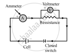
Draw the Labelled Diagram of an Electric Circuit Comprising ...
How to Read a Schematic - learn.sparkfun.com

Sample circuit diagrams from both the interactive labels (I ...

Learn.Digilentinc | Introduction to Circuits
The Schematic Diagram: A Basic Element of Circuit Design ...

11.1 Series circuits | Series and parallel circuits | Siyavula

Solved Question 3: The figure below shows a circuit diagram ...

Developing a Wiring Diagram (Circuit #1)

How to Create a Circuit Diagram | Lucidchart
Electronics Schematics: Commonly Used Symbols and Labels ...
Electronics Schematics: Commonly Used Symbols and Labels ...
Post a Comment for "41 circuit diagram with labels"